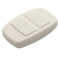
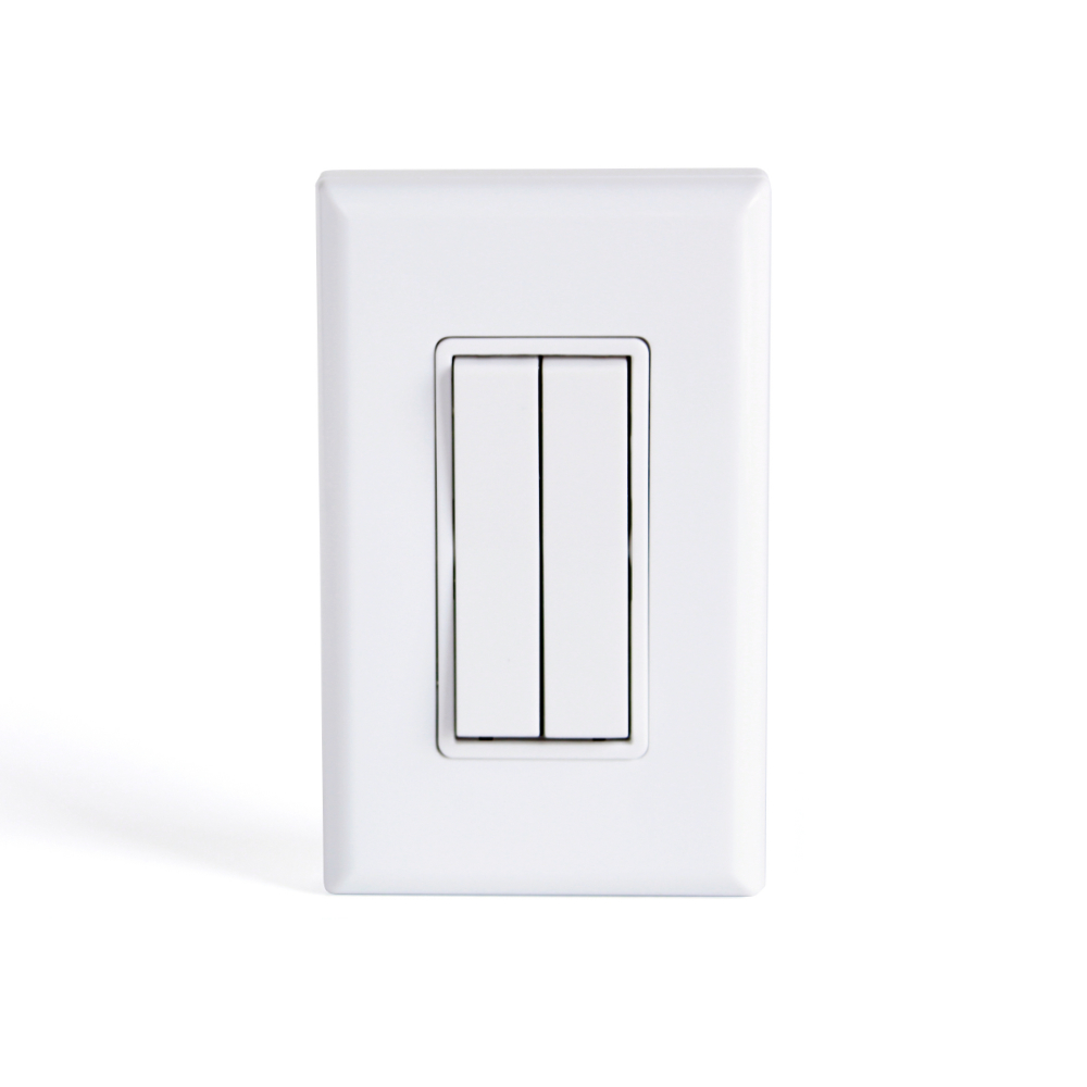
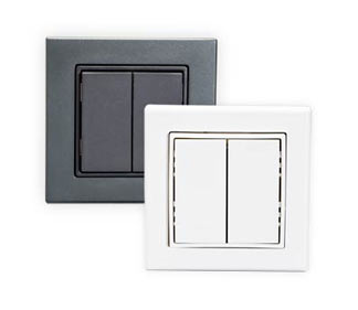
Self-Powered Dual Rocker ZigBee Wireless Light Switch
Part Numbers
ZBT-S2AWH (dual rocker, white)
.
.
Part Numbers
ZBT-S2AWH (dual rocker, white)
.
.
[one_third][box]
[/box]
Colors and Part Numbers
E3T-M04-SB24 . . . . . . . . . . . 450 sq. ft.
E3T-M15-SB24 . . . . . . . . . . 1500 sq. ft.
[/one_third]
[two_third_last][box]
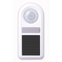
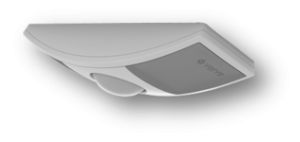
Description
The ILLUMRA Self-powered Wireless Occupancy Sensor is affordable, easy-to-use and easy-to-install. The occupancy sensor is powered using energy created from available room light; when motion is detected, the sensor transmits a wireless signal to ILLUMRA receivers connected to lights. This completely wireless sensor, used with ILLUMRA receivers, is an ideal solution for retrofit and new construction projects where building owners seek to reduce energy waste and save money.
Lighting accounts for one of the largest portions of a commercial building’s electric bill. Often, lights are left on unnecessarily causing both energy and money to be wasted. The occupancy sensor eliminates waste by ensuring lights in unoccupied areas are turned off. The sensor surface mounts without switch leg wires, making installation quick and easy and keeping labor costs to a minimum.[/box]
[table “” not found /]Downloads
Applications
Wiring Diagrams
[/one_third_last][/two_third_last]
[one_third][box]
[/box]
Colors and Part Numbers
E3T-M04-RB24 . . . . . . . . . . 450 sq. ft.
E3T-M15-RB24 . . . . . . . . . . .1500 sq. ft.
[/one_third]
[two_third_last][box]
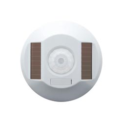
Description
The ILLUMRA Self-powered Wireless Occupancy Sensor is affordable, easy-to-use and easy-to-install. The occupancy sensor is powered using energy created from available room light; when motion is detected, the sensor transmits a wireless signal to ILLUMRA receivers connected to lights. This completely wireless sensor, used with ILLUMRA receivers, is an ideal solution for retrofit and new construction projects where building owners seek to reduce energy waste and save money.
Lighting accounts for one of the largest portions of a commercial building’s electric bill. Often, lights are left on unnecessarily causing both energy and money to be wasted. The occupancy sensor eliminates waste by ensuring lights in unoccupied areas are turned off. The sensor surface mounts without switch leg wires, making installation quick and easy and keeping labor costs to a minimum.[/box]
[table “” not found /]Downloads
Applications
Wiring Diagrams
[/one_third_last][/two_third_last]

Wireless Window/Door sensor receives top honors
ILLUMRA Self-powered Wireless Controls of Lindon, UT has been honored with a recognition by Building Operating Management in its selection of “2012 Top Products Award Winners.”
Lindon, UT November 1, 2012– Announcing a special recognition appearing in the January, 2012 issue of Building Operating Management. The Self-powered Wireless Window/Door sensor from ILLUMRA was selected for the following honor:
The Wireless Window/Door sensor is used to reduce energy consumption and equipment wear and tear in hotel rooms, condominiums, schools, and etc. by shutting off air conditioning equipment when Windows or Doors are open. The wireless sensor transmits radio frequencies to eliminate the time and cost of installing wires to the sensor. Additionally, the wireless door sensor reduces maintenance cost because it does not require batteries; instead it uses energy collected from ambient indoor light using small solar cell stores enough energy to operate for several days in complete darkness.
Jan Finlinson, Director from ILLUMRA Self-powered Wireless Controls commented on the recognition: “The fact that Building Operating Management included ILLUMRA Self-powered Wireless Controls in its selection of “2012 Top Products Award Winners,” signals that our constant efforts towards business excellence are paying off. We are proud to be included in this recognition.”
For more information on ILLUMRA Self-powered Wireless Controls, located in Lindon, UT please call 801-349-1200.
Contact Info:
ILLUMRA Self-powered Wireless Controls
Phone: 801-349-1200
Email Address: [email protected]
ILLUMRA Self-powered Wireless Controls Selected For “2012 Top Products Award Winners”.


Conference Room Lighting Controls
Small Office Occupancy Based Zone Lighting
Large Office Occupancy Based Zone Lighting
Commerical Lighting Control with wireless simplfies wiring in multiple locations within a commercial building.
A building owner decided to add switch locations when electrical work in a building had already been halfway completed. The new electrical plan called for luminaries in the building to be controlled from multiple locations had initially installed a single switch for each fixture. Pulling wires to the new switch locations was impractical. The completion date of the project was in jeopardy of slipping.
The architect and contractor used ILLUMRA self-powered wireless light switches occupancy sensors and ILLUMRA wired-in controllers to simplify wiring. Wireless switches installed at the desired new locations eliminated the need to run switch leg or traveler wires. Wiring was simplfied. Because the switches never need batteries, they will never require maintenance. Wireless relay controllers were installed to receive radio signals from the new ILLUMRA wireless light switches, occupancy sensors and control the luminaries. The project was successfully finished on-time.
 Wireless Rocker Switch |
 Controller |
 Ceiling Occupancy Sensor |
[one_third]
 – Faceplate (PTM257-Face-WH2)
– Backplate (AHP-DS-WH-BP-2)
– (2) Single Rocker Wireless Light
– Switches (ExT-S1AWH)
– Faceplate (PTM257-Face-WH2)
– Backplate (AHP-DS-WH-BP-2)
– (2) Single Rocker Wireless Light
– Switches (ExT-S1AWH)
 – Faceplate (PTM257-Face-WH2)
– Backplate (AHP-DS-WH-BP-2)
– (1) Single Rocker Wireless Light
– Switches (ExT-S1AWH)
– (1) Dual Rock Wireless Light
Switch (ExT-S2AWH)
– Faceplate (PTM257-Face-WH2)
– Backplate (AHP-DS-WH-BP-2)
– (1) Single Rocker Wireless Light
– Switches (ExT-S1AWH)
– (1) Dual Rock Wireless Light
Switch (ExT-S2AWH)
 – Faceplate (PTM257-Face-WH2)
– Backplate (AHP-DS-WH-BP-2)
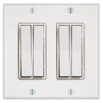
– (2) Dual Rocker Wireless Light
– Switches (ExT-S2AWH)
– Faceplate (PTM257-Face-WH2)
– Backplate (AHP-DS-WH-BP-2)
– (2) Dual Rocker Wireless Light
– Switches (ExT-S2AWH)
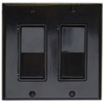 – Faceplate (PTM257-Face-BK2)
– Backplate (AHP-DS-BK-BP-2)
– (2) Single Rocker Wireless Light
– Switches (ExT-S1ABK)
– Faceplate (PTM257-Face-BK2)
– Backplate (AHP-DS-BK-BP-2)
– (2) Single Rocker Wireless Light
– Switches (ExT-S1ABK)
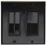 – Faceplate (PTM257-Face-BK2)
– Backplate (AHP-DS-BK-BP-2)
– (1) Single Rocker Wireless Light
– Switch (ExT-S1ABK)
– (1) Dual Rock Wireless Light
Switch (ExT-S2ABK)
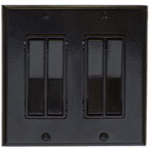
– Faceplate (PTM257-Face-BK2)
– Backplate (AHP-DS-BK-BP-2)
– (1) Single Rocker Wireless Light
– Switch (ExT-S1ABK)
– (1) Dual Rock Wireless Light
Switch (ExT-S2ABK)
Colors and Part Numbers
 White……………………………..E3T-S1AWH
 Black……………………………….E3T-S1ABK
White……………………………..E8T-S1AWH
Black……………………………….E8T-S1ABK
White……………………………..E9T-S1AWH
Black……………………………….E9T-S1ABK
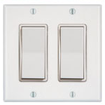
Because of the many variations of the 2-gang Wireless Light Switch the ordering process includes multiple part numbers. Scroll through the six different images on the product sliderto see what each switch variation looks like and the part numbers that are needed to order it.
[/one_third]
[two_third_last][box]
Description
Put multiple switches in one location with a 2-gang Wireless Light Switch. The variations allow 2, 3, or 4 switches at one location.[/box]
[table “” not found /]
[one_third]
Downloads
Applications
Wiring Diagrams
[/one_third_last][/two_third_last]

Colors and Part Numbers
White.................E9T-S1EWH
Black..................E9T-S1EBK
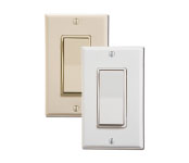
Description
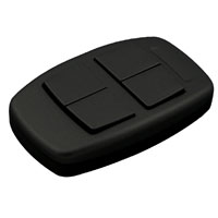
Control one light or one group of lights with the European Style Single Rocker Wireless Light Switch. The product is available in white or black, 902 MHz configurations, with a housing that resists tampering and theft. One switch can control an unlimited number of ILLUMRA controllers that are within range. Also available in Dual Rocker (European Style).
| E9T-S1Exx | ||
|---|---|---|
| Range | 50-150 feet (typical) | |
| Frequency | 315 868 or 902 MHz | |
| Power Supply | Self-generated when switch is pressed | |
| Buttons | 2 Buttons (1 rocker) | |
| Output Channels | Only limited by number of receivers in range | |
| Dimensions | 3.16(W) x 3.16(H) x 0.40(D) inches | |
| Operating Temperature | -13° to +149°F (- 25° to + 65°C) | |
| Radio Certifications | FCC (U.S.): SZV-PTM200C / SZV-PTM200 – IC (Canada): 5713A-PTM200C / 5713A-PTM200 | |
| Addressing | Factory set unique ID (1 of 4 billion) |
[one_third]
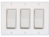 – Faceplate (PTM257-Face-WH3)
– Backplate (AHP-DS-WH-BP-3)
– (3) Single Rocker Wireless Light
Switches (ExT-S1AWH)
– Faceplate (PTM257-Face-WH3)
– Backplate (AHP-DS-WH-BP-3)
– (3) Single Rocker Wireless Light
Switches (ExT-S1AWH)
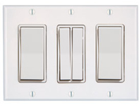 – Faceplate (PTM257-Face-WH3)
– Backplate (AHP-DS-WH-BP-3)
– (2) Single Rocker Wireless Light
Switches (ExT-S1AWH)
– (1) Dual Rocker Wireless Light
Switch (ExT-S2AWH)
– Faceplate (PTM257-Face-WH3)
– Backplate (AHP-DS-WH-BP-3)
– (2) Single Rocker Wireless Light
Switches (ExT-S1AWH)
– (1) Dual Rocker Wireless Light
Switch (ExT-S2AWH)
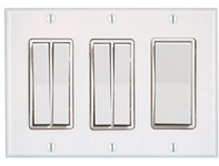 – Faceplate (PTM257-Face-WH3)
– Backplate (AHP-DS-WH-BP-3)
– (1) Single Rocker Wireless Light
Switch (ExT-S1AWH)
– (2) Dual Rocker Wireless Light
Switches (ExT-S2AWH)
– Faceplate (PTM257-Face-WH3)
– Backplate (AHP-DS-WH-BP-3)
– (1) Single Rocker Wireless Light
Switch (ExT-S1AWH)
– (2) Dual Rocker Wireless Light
Switches (ExT-S2AWH)
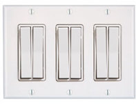 – Faceplate (PTM257-Face-WH3)
– Backplate (AHP-DS-WH-BP-3)
– (3) Dual Rocker Wireless Light
Switches (ExT-S2AWH)
– Faceplate (PTM257-Face-WH3)
– Backplate (AHP-DS-WH-BP-3)
– (3) Dual Rocker Wireless Light
Switches (ExT-S2AWH)
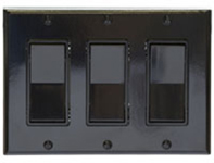 – Faceplate (PTM257-Face-BK3)
– Backplate (AHP-DS-BK-BP-3)
– (3) Single Rocker Wireless Light
Switches (ExT-S1ABK)
– Faceplate (PTM257-Face-BK3)
– Backplate (AHP-DS-BK-BP-3)
– (3) Single Rocker Wireless Light
Switches (ExT-S1ABK)
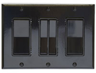
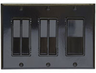
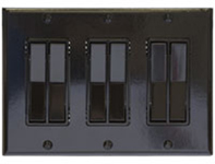
Colors and Part Numbers
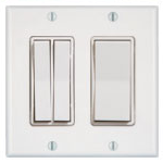
Because of the many variations of the 2-gang Wireless Light Switch the ordering process includes multiple part numbers. Scroll through the six different images on the product sliderto see what each switch variation looks like and the part numbers that are needed to order it.
[/one_third]
[two_third_last][box]
Description
Put multiple switches in one location with a 3-gang Wireless Light Switch. The variations allow 3, 4, 5, or 6 switches at one location.[/box]
[table “” not found /]
[one_third]
Downloads
Applications
Wiring Diagrams
[/one_third_last][/two_third_last]
Colors and Part Numbers
White.......................E9T-S2EWH
Black........................E9T-S2EBK
Colors and Part Numbers
White..........E9T-S2HWH
Black...........E9T-S2HBK
[one_third][box]
[/box]
Colors and Part Numbers
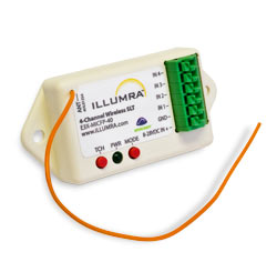
8-28VDC………………………E3T-MICFP-40
[/one_third]
[two_third_last][box]
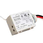
Description
The ILLUMRA 4 Channel Switch Leg Transmitter (SLT Power Sensor) replaces wires between an electrical load and a switch with an RF control signal. The SLT connects to a standard switch and controls loads that are connected to ILLUMRA receivers.[/box]
[table “” not found /]Downloads
Applications
Wiring Diagrams
[/one_third_last][/two_third_last]

Colors and Part Numbers
E9T-MDCCP - Solar Powered
E9T-MCS - Solar Powered with Battery back-up
[one_third][box]
[/box]
Colors and Part Numbers
E3X-R02-5IBTP (24V)
E3X-R12-5IBTP (120V)
E3X-R24-5IBTP (240V)
E3X-R27-5IBTP (277V)
[/one_third]
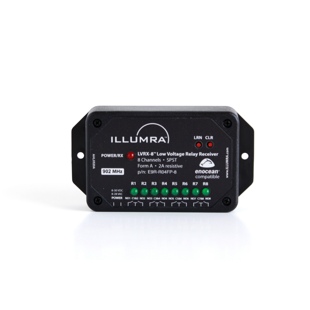
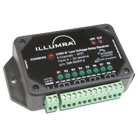
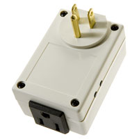
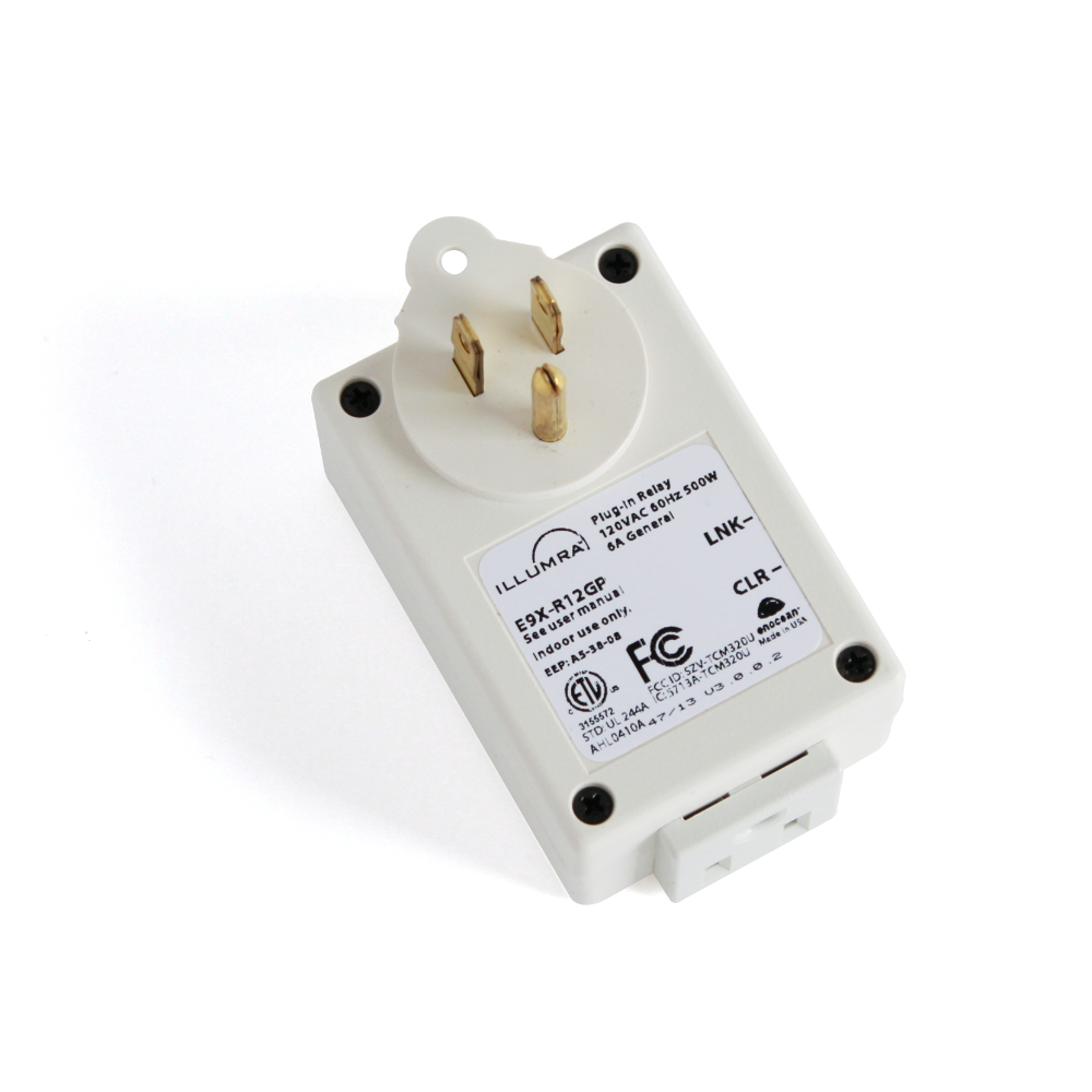
[two_third_last][box]
Description
The 5-wire Relay Receiver + Repeater receives signals from ILLUMRA self-powered wireless light switches and sensors and re-broadcasts the signals an additional 50-150 feet. The repeater is also a relay receiver and can be used to control one electrical load (see Specifications). Wire the repeater in a location that allows it to increase the range of any ILLUMRA wireless control network.[/box]
[table “” not found /]Downloads
Applications
Wiring Diagrams
[/one_third_last][/two_third_last]
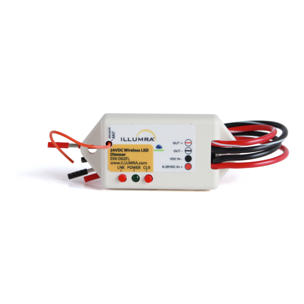
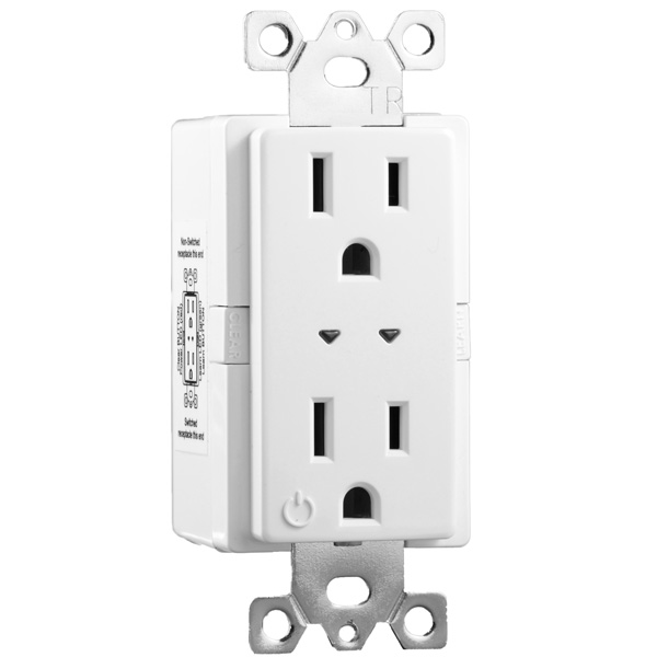
Part Numbers
E9X-D02FL (With wireless capability & Flying Lead Connections)
NWO-D02FP (Without wireless capability)
![]()
801-349-1200
Lindon, UT