

ILLUMRA Wireless Valve Actuator Reduces Heating Costs
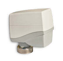
A new, multi-function wireless valve actuator that can be integrated with building automation systems, through an existing building control gateway, will be available in the US and Canada on February 1, 2011, announced Jan Finlinson, President of ILLUMRA. The Wireless M3 Valve Actuator is designed for use on continuous closed-loop control systems and communicates based on EnOcean technology. ILLUMRA, the premier supplier of self-powered wireless lighting and HVAC controls in North America, is the exclusive distributor of the Wireless M3 Valve Actuator in the US and Canada.
 The new wireless valve actuator is produced by Kieback & Peter, the 84-year old German-based, family-owned company. Kieback & Peter is one of the leading providers of the European market’s building automation systems. “We are pleased to launch our wireless valve actuator in the US through ILLUMRA. Their proven track record of experience in energy efficiency systems integration and training makes them the ideal, value-added partner for our business in the US and Canada, “ said Hans Symanczik, Kieback & Peter’s GmbH & Co., Sales & Marketing Management.
“ILLUMRA’s Wireless M3 Valve Actuator is revolutionary,” explained Finlinson. “Now you can control temperature settings within your entire building or individual rooms with intelligent devices.” The ILLUMRA Wireless M3 Valve Actuator, named for its three-in-one functionality, exceeds the scope of traditional actuators. Its ability to integrate into complex automation systems and serve as a self-sufficient room controller opens up new possibilities in room automation, added Finlinson.
According to Finlinson, the device is easy to install since it does not require installation of traditional wiring. In retrofits, the installation can be completed without disrupting or affecting existing building systems.
The ILLUMRA Wireless M3 Valve Actuator will make opening windows to control excessive heat a thing of the past. Aging radiator actuators and outdated heating system designs cannot effectively control heat supply and opening windows became the quick fix to overheating. That solution has been the bane of many high-rise commercial building owners who face escalating fuel costs each season. “Our Wireless M3 Valve Actuator provides building owners and property managers with an integrated energy efficiency system that provide excellent ROI on initial product and installation costs within an average 2 year period. Reduced Maintenance Costs. Maintenance is a seamless process based on battery replacement every three years. Battery status information is reported through the building automation system. “The potential of ILLUMRA’s Wireless M3 Actuator to reduce building heating costs in both retrofit and new construction applications is an invaluable tool for owners, builders and contractors,” said Finlinson.
Wireless Access Control Door Lock

120V 3-Wire Basic (ExR-R12-3HOTP)
Link Mode: Momentary
Application
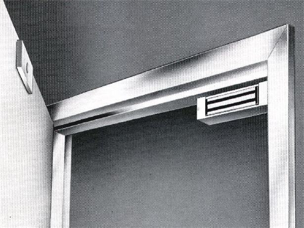
Wireless access control door Lock on doors in conference rooms, offices, hospital rooms, and classrooms.
Scenario
A large institution with hundreds of offices wanted the occupants of their offices to be able to release the magnetic door latches on their office doors from their desks. The building wasn’t originally designed to accommodate such a requirement.
Solution
Administrators identified Illumra self-powered wireless controls as a viable solution. Self-powered switches were mounted on the underside of the desk, within reach of the person sitting at the desk. Wireless relay receivers were connected to the magnetic latch, thereby allowing control of the door from a seated position. Installing these controls increased worker efficiency and convenience.
Products
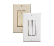
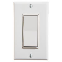
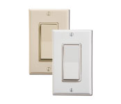 Single Rocker Switch |
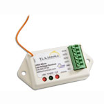
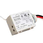 Receiver |
X= (3) 315 MHz (9) 902 MHz
Wireless Boat Dock Lighting

Short Range: Boat to Dock 3 Wire 120V Basic Light Switch & Receiver
Short Range: Boat to Dock, Dock to House, House to Dock 3 Wire 120V Basic Light Switch & Receiver
Long Range: Boat Dock to House Industrial Wireless Relay (IWR)
Application
Wireless boat dock lighting from dock to house and house to dock. The distance from Boat Dock to House was 100 yards plus. A need to control floodlighting at the dock and a circuit of yard lights from switches at two locations: the boat house and home. Turn on lights at the boat dock on approach to the dock in the evening.
Scenario
The Marine Light Contols selected exceeded the range limit for ILLUMRA basic transmitters and receivers. The switches at the boat house effectively control ILLUMRA receivers wired behind the flood lights at the boat house. The wireless signals from switches inside the home do not reach ILLUMRA receivers down at the boat house.
Solution
The ILLUMRA long range Marine Light Controls was the solution. The Illumra Industrial Wireless Relay (IWR) set was installed at the boat dock and the house . The wireless boat dock lighting request was solved with a wireless light switch placed near the captain’s chair and the receiver installed at the boat dock lights. This allows the boat captain to turn on the lights from his captains chair on approach approximately 150 -300 feet out.
Products
|
Single Rocker Switch |
Receiver |
x = (3) 315 MHz (9) 902 MHz
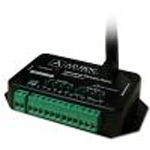
Long Range Receiver: Zigbee 2.4 GHz
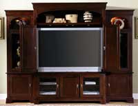
Remote Entertainment Center Lighting
Application
Control lights in entertainment center from across the room.
Scenario
A homeowner purchased a new entertainment center and wanted to be able to control the lights in it from across the room. The lights in the entertainment center normally plug into an electrical outlet.
Solution
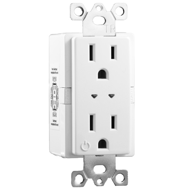
ILLUMRA self-powered wireless switches, and a plug-in dimmer/relay solved the problem and allowed the homeowner to control the mood lights in the entertainment center from several locations throughout the room, including the sofa. The plug in dimmer/relay was simply plugged into an outlet and the lights were plugged into it. The switches were attached to the surface of the walls, without cutting into them. A hand-held remote can be used from a seated position on the comfortable sofa. The system is compatible with dimmable bulbs and on/off fluorescent bulbs.
Products
|
 |
| E3T-S1AWH | E3T-S2AWH |
 |
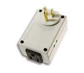 |
| E3T-S2HWH | E3R-D12GP-1 |
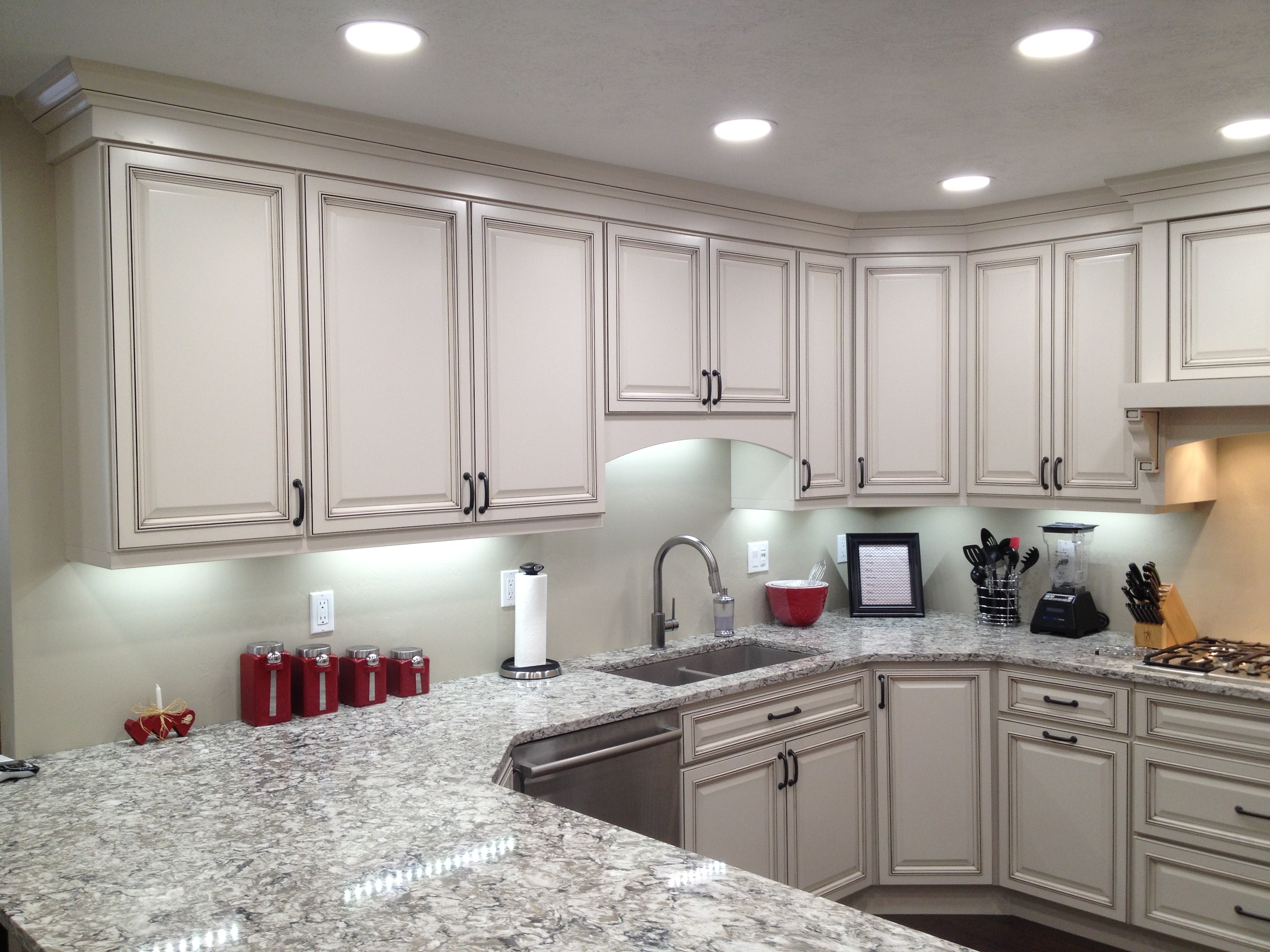
Wireless LED Under Cabinet Lighting
Application
Wireless LED under cabinet lighting with wired or wireless control.
Scenario
A homeowner wants to add LED under cabinet lights to the home after the kitchen had been built. Unfortunately, running wires to a new switch was not a practical solution.
Solution
ILLUMRA wireless under cabinet lighting, with their self-powered wireless switches, and wired or wirless dimmer solved the problem and allows homeowner to control the new or remodel under cabinet luminaries from several locations throughout the kitchen. The switches can be attached to the surface of the walls, without cutting into them or existing switch receptacle. The system is compatible with LED 12 or 24V LED lighting.
Products
|
Single Rocker Switch |
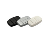
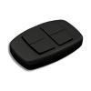 Handheld Wireless Switch |
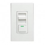
 Wired Dimmer
|
x= (3) MHz (9) Mhz
xx = FP Wire Trap Connector
xx = FL Flying Lead Wires
Yacht to Dock Lighting

120V 3 wire Basic Wiring Diagram (E9X-R12-3HOTP)
120V 3 Wire 3 Way Wiring Diagram(E9X-R12-3HOTP)
Application
Yacht to Dock lighting
Scenario
The Yacht owner wants to turn on the Dock lights from his Yacht while on approach. Yacht to Dock lighting will make departures and arrivals at night easier and safer
Solution
Yacht to Dock lighting was achieved with a ILLUMRA wire-in relay connecting to the light fixtures on the dock. ILLUMRA self-powered wireless light switches were installed in the yacht and an ILLUMRA self-powered, hand-held wireless remote control was located at the helm, permitting the captain or the occupants of the ship to safely control the lights while aboard.
Products
 Single Rocker Switch  Handheld Wireless Switch
|
Controller 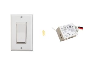 Basic Wireless Switch Kit |
x – (3) 315 Mhz (9) 902 MHz
Boyd’s Test Page
[one_third]
120V 3 wire Basic Wiring Diagram (E9X-R12-3HOTP)
120V 3 Wire 3 Way Wiring Diagram(E9X-R12-3HOTP)[/one_third][two_third_last]
[box]
Application
[/box]
Yacht to Dock lighting
[box]
Scenario
[/box]
The Yacht owner wants to turn on the Dock lights from his Yacht while on approach. Yacht to Dock lighting will make departures and arrivals at night easier and safer
[box]
Solution
[/box]
Yacht to Dock lighting was achieved with a ILLUMRA wire-in relay connecting to the light fixtures on the dock. ILLUMRA self-powered wireless light switches were installed in the yacht and an ILLUMRA self-powered, hand-held wireless remote control was located at the helm, permitting the captain or the occupants of the ship to safely control the lights while aboard.
[box]
Products
[/box]
|
|
|
| ExT-S1xxx | ExX-R12-3HOTP | ExT-S2Hxx / ExT-S2Hxx |
x – (3) 315 Mhz (9) 902 MHz
[table “” not found /]
[table “” not found /]
[/two_third_last]
Commercial Lighting Control with Wireless

Conference Room Lighting Controls
Small Office Occupancy Based Zone Lighting
Large Office Occupancy Based Zone Lighting
Application
Commerical Lighting Control with wireless simplfies wiring in multiple locations within a commercial building.
Scenario
A building owner decided to add switch locations when electrical work in a building had already been halfway completed. The new electrical plan called for luminaries in the building to be controlled from multiple locations had initially installed a single switch for each fixture. Pulling wires to the new switch locations was impractical. The completion date of the project was in jeopardy of slipping.
Solution
The architect and contractor used ILLUMRA self-powered wireless light switches occupancy sensors and ILLUMRA wired-in controllers to simplify wiring. Wireless switches installed at the desired new locations eliminated the need to run switch leg or traveler wires. Wiring was simplfied. Because the switches never need batteries, they will never require maintenance. Wireless relay controllers were installed to receive radio signals from the new ILLUMRA wireless light switches, occupancy sensors and control the luminaries. The project was successfully finished on-time.
Products
|
Wireless Rocker Switch |
Controller |
 Ceiling Occupancy Sensor |
Wireless Landscape Lighting Control

Wireless Switch Leg (ExK-K11-WH, ExK-L11-WH, ExK-M11-WH)
120V 3-Wire Basic (ExX-R12-3HOTP)
Application
Landscape lighting control switch.
Scenario
The building owner wanted to be able to control the new landscape lighting with the existing switch that controls the porch light and from a new location in the master suite. The problem was that the landscape lighting was installed after the building was built, and there was not an easy way to install new wires to the desired switch locations.
Solution
The ILLUMRA Wireless landscape lighting controls include a self-powered wireless switch, a control extender sensor, and wireless relays. A self-powered wireless switch was installed near the bed in the master suite. The control extender sensor was installed in the porch light fixture, and wireless relays were installed to control the transformers feeding the low-voltage garden lights.
Products
|
Single Rocker Switch |
Receiver |
 Control Extender |
Wireless Lighting Controls – Basic Switch Kit

Basic: Switch & Receiver Solution
3-Way: (2) Switches & Receiver Solution
Applications
Case Studies
Application
Finish projects faster! Wireless Lighting Controls when compared with traditional switch solutions allow contractors to finish projects in 1/3 less time and use 1/3 less wire when using ILLUMRA Self-powered Wireless Controls.
Scenario
Traditional Switch locations may require difficult and costly wiring.
- No flexibility in placement of switches
- Can’t configure which lights are switched together
Solution
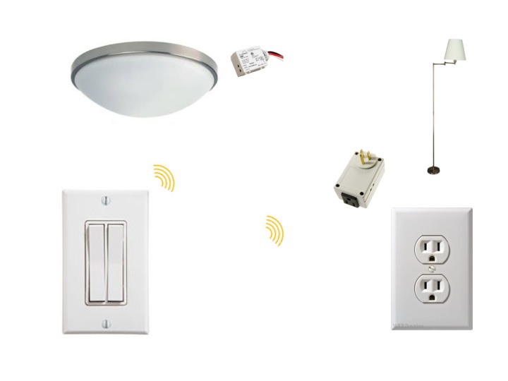
Add wireless lighting controls to ceiling lights and floor lamps.
- Lamps and furniture can be easily reconfigured
- A single switch controls lights on multiple circuits
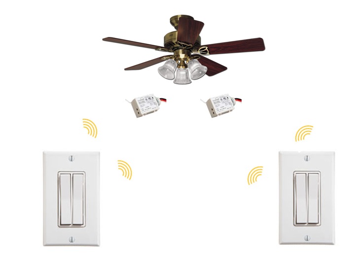
Wireless Fan and Light Control

Application
Finish projects faster! When compared with traditional switch solutions, contractors finish projects in 1/3 less time and use 1/3 less wire when using ILLUMRA Self-powered Wireless Controls.
Scenario
Using electric wire and standard toggle or Decora style switches to control a light and fan
- Cut holes in the wall and ceiling to install wires between the fixture and switches
- Install new switch boxes to house the 2-gang switches
Solution
No wire or switch boxes needed to install wireless switches
- One receiver controls the light and the other receiver controls the fan
- Both receivers are installed into the receptacle behind the fixture
Products
Wireless Water Feature Control

120V 3-Wire Basic (ExX-R12-3HOTP)
Application
Landscape water feature control switch.
Scenario
The home owner needed to be able to control the waterfall from a location within the home. The problem was that there was not an easy way to get wires from the wiring box near the pump to the inside of the walls of the home.Solution
ILLUMRA self-powered wireless switches were used. Switches were mounted on the surface of the wall in the home in several locations without cutting into the walls and without the need to install new wires. The ILLUMRA relay receiver was installed in the weather-proof, plastic wiring box near the pump.
Products
|
Single Rocker Switch |
Receiver
|
Basic Wireless Switch Kit
X = (3) 315 MHz (9) 902 MHz
Hospital Patient Room Lighting with Wireless

Application
Hospital patient room lighting with wireless control provides the ability to dim lights from mobile location, such as a hospital bed.
Scenario
A hospital needed to give recovering patients the ability to dim the light fixture in the room without a cumbersome tether or control cable. The controller had to be easy to handle, actuate, and needed to be attached to the bed so as to be easily accessible. Another requirement was that any wireless control signals must not interfere with other hospital instruments.
Solution
Hospital Patient room lighting with wireless control allowes patients to use ILLUMRA wireless plug-in dimmers and ILLUMRA wireless hand-held remote controls to provide convenient dimming control from the bed. The hand-held controls were outfitted with special recoiling tethers and attached to the armrest, so they would always be accessible to the patient. The self-powered wireless remote controls never “go dead” because they don’t contain batteries. ILLUMRA products do not interfere with sensitive hospital instruments.
Products
|
|
| E3T-S2HWH | E3R-D12GP-1 |
Gas Station Lighting

CUV – Controls Extender / Wireless Switch Leg solution
Application
Add the ability to control gas station lighting at the fuel pump using an existing daylight sensor mounted above the canopy roof without running new wires to the pumps.
Scenario
An oil company wanted to conserve electrical energy at each of its outlet stores by turning off the advertisement lights atop each of the pumps during the day. Installing daylight sensors on the pumps themselves would be ineffective because the overhead canopy lights would provide enough light to keep the pump lights always turned off. Installing new wiring to the pumps was not an option because of its expense.
Solution
A Wired Light Sensor and ILLUMRA transmitters and receiver/relays were used. The sensor/transmitter monitors the state of the overhead canopy lights, which were already daylight-controlled. It sends a wireless control signal to the relay receivers installed in the light fixtures on the pumps below, causing the lights to be off whenever the overhead canopy lights are off, and vice-versa. No new wiring was needed and the oil company was able to cut its electricity consumption.
Products
|
ExX-R12-3HOTP ExT-S1Axx |
Ext-R12-2INTP E9X-CUV |
| |
Automatic Generator Control

Generator Disconnect (E3K-K11-WH)
Application
Automatic Generator Control System prevents overloading of a backup generator.
Scenario
A facility, equipped with a backup generator, has some power-hungry equipment, which the generator is incapable of running. They want to automatically disconnect the power-hungry equipment from the supply circuit whenever the generator comes on-line, thereby preventing the generator from overloading.
Solution
The ILLUMRA Control Extender power sensors can be used to detect the presence of a supply voltage, and transmit a control signal to a corresponding relay receiver. The Control Extender power sensor was connected to the AC output of the generator. In this case, the relay receiver drove the coil of a much larger contactor, which is capable of switching the power-hungry equipment. The ILLUMRA components were installed quickly and help the facility to run more smoothly.
Products
Marina Light Controls
Marina Light Controls

Application
An ILLUMRA customer had a boat house and dock a distance away from his home. He needed to control two floodlights down at the dock and a circuit of yard lights from switches at two locations: the boat house and his home.
Scenario
The distance down to the boat house just exceeds the range limit for ILLUMRA transmitters and receivers. The switches at the boat house effectively control ILLUMRA receivers wired behind the flood lights at the boat house. The wireless signals from switches inside the home do not reach ILLUMRA receivers down at the boat house. The yard lights line a path down to the boat house where they are connected in circuit with one floodlight and one ILLUMRA relay receiver.
Solution
The ILLUMRA relay receiver connected to the yard lights was removed from its location at the boathouse and the circuit was reconnected without the receiver inline. An ILLUMRA Relay Receiver + Repeater was connected to the yard light circuit midway between the home and the boathouse. The Relay Receiver + Repeater is programmed to respond to an ILLUMRA remote light switch in the home to control the electrical load connected to the device. The Relay Receiver + Repeater also acts as a repeater for all transmitting switches in the home. The unit receives signals and rebroadcasts them down to receivers at the boat house.
Products
E3T-S1AWH
|
E3X-R12-5IBBP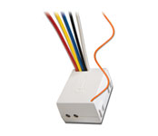 |


Power Pack w/Relay
[one_third][box]
[/box]
Colors and Part Numbers
120/230/277 VAC. . . . . NWO-R12-R27NP
[/one_third]
[two_third_last][box]
Description
Power Packs are designed to be flexible enough to control almost any lighting or HVAC load. They are excellent for any application which requires high voltage switching through low voltage controls. By linking power packs with ILLUMRA receivers, an almost unlimited number of configurations can be obtained.
Power Packs consist of a transformer and high current relay that are combined into one small, powerful package. The transformer has a primary high voltage input and a secondary, low voltage output (24 VDC, 114 mA with relay connected). The secondary low voltage output provides operating power to ILLUMRA receivers, which in turn, control the relay in the power pack, which then controls the lighting system.[/box]
[table “” not found /][table “” not found /]
[table “” not found /]
[one_third]
Downloads
- Datasheet [/one_third][one_third]
Applications
- Coming Soon [/one_third][one_third_last]
Wiring Diagrams
- Coming Soon
[/one_third_last][/two_third_last]
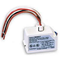
Power Pack
[one_third][box]
[/box]
Colors and Part Numbers
120/230/277 VAC. . . . . NWO-RHV-0D0 (Black)
[/one_third]
[two_third_last][box]
Description
Power Packs are designed to be flexible enough to control almost any lighting or HVAC load. They are excellent for any application which requires high voltage switching through low voltage controls. By linking power packs with ILLUMRA receivers, an almost unlimited number of configurations can be obtained.
Power Packs consist of a transformer and high current relay that are combined into one small, powerful package. The transformer has a primary high voltage input and a secondary, low voltage output (24 VDC, 150 mA with relay connected). The secondary low voltage output provides operating power to ILLUMRA receivers, which in turn, control the relay in the power pack, which then controls the lighting system.[/box]
[table “” not found /][table “” not found /]
[table “” not found /]
[one_third]
Downloads
- Datasheet [/one_third][one_third]
Applications
- None Available [/one_third][one_third_last]
Wiring Diagrams
- Coming Soon
[/one_third_last][/two_third_last]

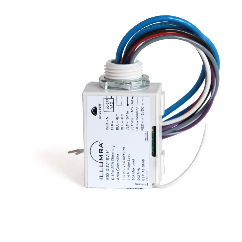
Wireless 0-10 Volt Primary and Secondary Dimming Controller Tutorial
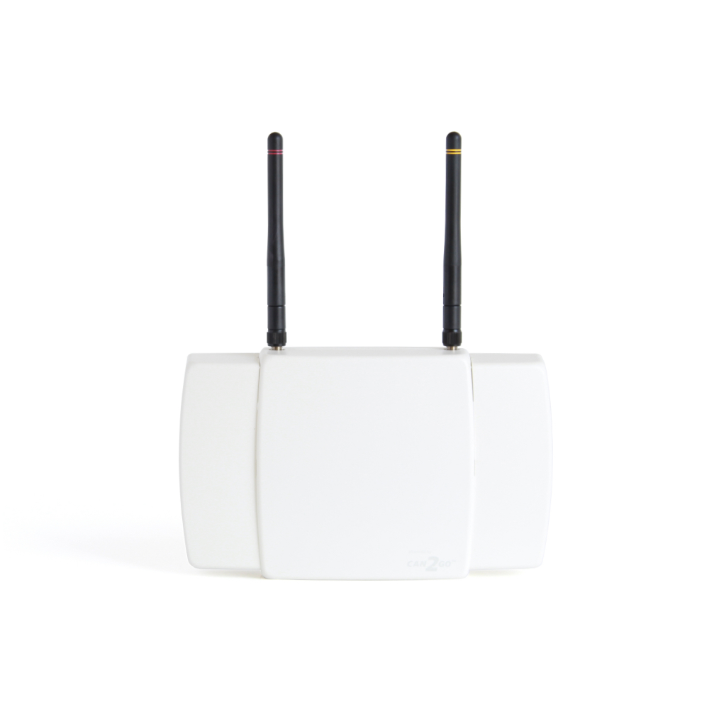
Demonstration of ILLUMRA 0-10V Primary / Secondary (Master / Slave) remote LED dimmer controls. Also shows battery-free wireless switches and occupancy sensors being linked to wireless 0-10V Area Controllers. The Area Controller features 20A load switching capacity and 0-10V dimming circuit rated to control dimming of up to 200 fixtures. The system uses wireless motion sensors to operate occupancy sensing mode with the lights turning on with motion or in vacancy mode with a manual switch and lights turning off automatically when no motion is detected. Up to 25 Wireless switches may be used to control the lights from multiple locations.
More information: